| Features | |
|
|
| Applications | 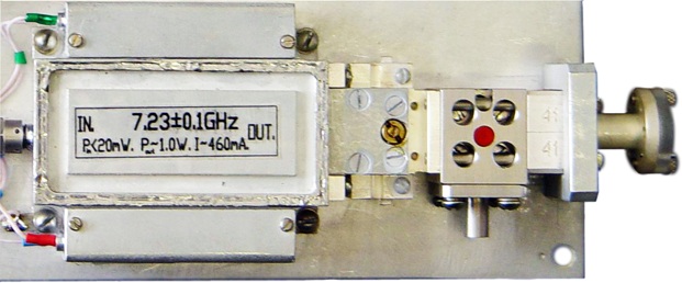 |
|
Description
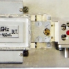
ELVA–1 series IMPATT Active Frequency Multipliers IAFM are really unique devices providing an outstanding performance in terms of high efficiency and high output power. Available in multiplication factor up to 25 inone device they cover the output frequency range of 20 to 180 GHz using centimeter-wave range source. They are capable of handing very high input power without damage. Different IAFM’s would operate with the same centimeter-wave range pumping source. For example, on the picture above you can see the pumping source (20 mW, 7.2775 GHz) and three different multipliers: IAFM-28 (5th harmonic, 36.3875 GHz), IAFM-15 (8th harmonic, 58.2200 GHz) and IAFM-10 (13th harmonic, 94.6075 GHz). The phase and amplitude stability of the output signal defined by the quality of the pumping source. It is possible to achieve Hz resolution on 150 GHz using state-of-the-art synthesized cm-wave source. The frequency multipliers are designed as a module, that consists of centimeter-wave high power preamplifier, a multiplier itself, band-pass filter and isolator. Current stabilizer included for reliable, trouble-free operation. The band-pass filter rejects the side band noise of the source on about -50 dB. That allows to use the device as low noise solid state LO, if intermediate frequency is higher then the frequency of rejection. The input of multiplier is a coaxial connector, and the output is a waveguide flange
Specificifications
| Model Number | IAFM -28 | IAFM -22 | IAFM -19 | IAFM -15 | IAFM -12 | IAFM -10 | IAFM -08 | IAFM -06 |
| Frequency Band | Ka | Q | U | V | E | W | F | D |
| Frequency Range, GHz* | 26.5-40 | 33-50 | 40-60 | 50-75 | 60-90 | 75-110 | 90-140 | 110-180 |
| Maximum Power Output**, mW | 150 | 150 | 120 | 100 | 50 | 30-50 | 15-30 | 10-20 |
| Input signal power, mW | 30-50 | 30-50 | 30-50 | 30-50 | 30-50 | 30-50 | 30-50 | 30-50 |
| Multiplication factor | 5-8 | 6-10 | 7-10 | 8-13 | 10-15 | 14-18 | 18-24 | 19-25 |
| DC Power, V/A | +12/0.6
-12/0.01 +50/0.15 |
+12/0.6
-12/0.01 +45/0.15 |
+12/0.6
-12/0.01 +45/0.15 |
+12/0.2
-12/0.01 +35/0.15 |
+12/0.6
-12/0.01 +35/0.2 |
+12/0.6
-12/0.01 +27/0.2 |
+12/0.6
-12/0.01 +24/0.2 |
+12/0.6
-12/0.01 +24/0.26 |
| * Operation bandwidth 3-5%. Upon request 10% version is available. | ||||||||
| ** Values are presented for the middle frequency of the frequency band |
| Common specifications | |
| Output power flatness within the 1% band width (max) | 1.5 dB |
| Rejection of adjacent harmonics (min) | 40 dB |
| AM noise inserted (max) | -130 dBc/Hz (white noise) |
| VSWR | 1:1.3 |
There is no additional noise produced by IAFM-XX in comparing with passive multipliers. It can be estimated using the formula: Noise of pumping source +20Log(N) dBc/Hz. For example, if 7 GHz pumping source has -120 dBc/Hz on 10 kHz offset from the carrier, after frequency multiplication on a factor of 20 the noise of 140 GHz source on 10 kHz offset will be -120 dBc/Hz+20Log(20) = -94 dBc/Hz.
Series IAFM-XX are designed for high reliability and applications in hard environments. The operating temperature range: minus 50 to plus 70 °C and life time is equal to 50000 hours. Each model may be produced with the possibility of the fast output power switching. 1 ns time of on/off switching is allowed.
Optionally the following items would be supplied to meet customer requirements:
- Complete very stable solid state millimeter wave source, that consists of the following:
- Transistor oscillator stabilised by the dielectric resonator (DRO). 6-8 GHz, 10 mW output, 10-6 frequency stability. The stability would be increased upon request using a temperature stabilization scheme.
- Accuracy of frequency adjustment is about 5-50 MHz. The adjustment is provided on the factory according to customer requirements.
- Millimeter wave sweeper on the base of Varactor Controlled Oscillator (6-8 GHz, 10 mW). Other elements of the scheme are the same as above. Typical bandwidth is 0.5-1%.
- The frequency bandwidth would be also increased upon request. The limit is the distance between nearest harmonics, so it is impossible to provide the bandwidth more than the pumping frequency. The real bandwidth would be about 50-80% of the initial (pumping) frequency.
- IMPATT Injection-Locked Amplifiers IILA series to increase the output power.
- Phase or amplitude modulator on the base of fast P-I-N switch FPS series.
- Amplitude regulator on the base of Voltage Controlled Attenuator VCVA series.
- Power supply for AC Input Voltages 110 V, 60Hz; 220 V, 50 Hz.