| Features | Download Datasheet | ||||||||||||||||||||||||||||||||||||||||||
|
|
||||||||||||||||||||||||||||||||||||||||||
| Applications |  |
||||||||||||||||||||||||||||||||||||||||||
|
|||||||||||||||||||||||||||||||||||||||||||
| Description | |||||||||||||||||||||||||||||||||||||||||||
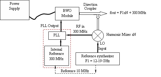
| Phase lockable SGMW-PLL series is based on standard SGMW series. External PLL circuit with reference synthesizer 12-19 GHz allow to get full waveguide tunable synthesizer with high output power. Block schematic diagram of SGMW-PLL system is presented below | |||||||||||||||||||||||||||||||||||||||||||
 |
|||||||||||||||||||||||||||||||||||||||||||
|
Figure 1. Block schematic diagram of SGMW-PLL unit set up Specifications |
|||||||||||||||||||||||||||||||||||||||||||
How to order Specify Model Number SGMW-PLL-X-A, where X – type of BWO tubes, V– power supply with BWO-V, VE – power supply with BWO-V and BWO-E, A – length of cable in meters. |
|||||||||||||||||||||||||||||||||||||||||||