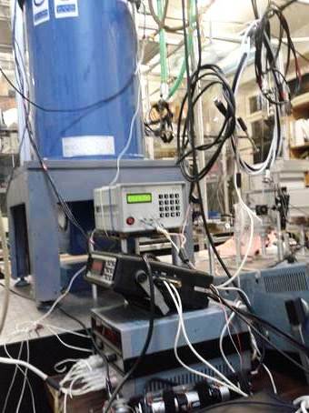
ELVA-1 71-76 GHz Frequency Synthesizer is intended for studying the phenomenon of optically detected magnetic resonance (ODMR), scientists study the behavior of magnetic nanostructures, such as quantum dots and quantum wells.
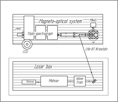
While irradiating nanostructure samples using microwave signal from the 71-76 GHz Frequency Synthesizer the researchers activate spin phenomena in semiconductors including diluted magnetic semiconductors and semiconductor nanostructures, thereby speeding up experiments. The nanostructure sample is placed into a helium cryostat at temperatures close to absolute zero. See block diagram of research bed for understanding of 71-76 GHz Frequency Synthesizer role (marked as MWG).


The study is being conducted in order to create memory elements for quantum computers. The development of quantum (optical) computer is a mega-project, which a lot of laboratories around the world work on. The goal is to develop a supercomputer of the future with enormous speed at a micro size. 71-76 GHz Frequency Synthesizer is intended for the continuous generation of the harmonic signals in the range 71-76 GHz and can operate in the following modes:• «CONTINUOUS WAVE» (CW) – continuous generation mode of reference frequency signal;
• «CONTINUOUS WAVE» (CW) – continuous generation mode of reference frequency signal with amplitude modulation;
• «FREQUENCY SWEEP» (FS) – sweep mode generator (sweeper).
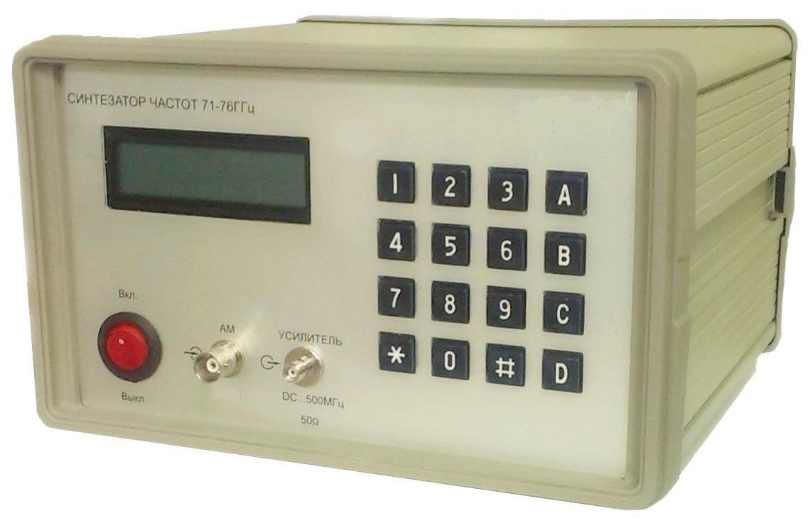
The synthesizer has a built-in keyboard for direct input of the output frequency settings on the front panel. It is also equipped with a 2-line LCD display, which displays information about the frequency and other signal parameters. Built-in USB-HID interface allows remote computer-aided device control. «71-76 GHz Synthesizer remote control» software is included in the shipment for this purpose.

71-76 GHz Frequency Synthesizer Specifications:
| Parameter | Value | |
| General Specs | ||
| 1 | Frequency range | 71 – 76 GHz |
| 2 | Frequency Resolution | 0.1 MHz |
| 3 | The highest output power level | 20 dBm |
| 4 | Settings for power level range attenuation | 0 – 35 dB |
| 5 | Resolution of output power attenuation | 0.5 dB |
| 6 | The output waveguide flange | 20×20 mm |
| 7 | The output waveguide channel | 3.6×1.8 mm (4) |
| 8 | Remote Management Interface | USB-HID |
| 9 | LED LCD display modes | Monochrome 2-line LCD |
| 10 | Power supply | 24 V (DC), 20 W |
| 11 | Operating temperature range | +10 … +50 °C |
| 12 | Dimensions | 137х210х210 mm |
| 13 | Net Weight | 3.3 kg |
| Frequency Sweep Specs | ||
| 1 | Sweep mode | Linear |
| 2 | Radio pulse duration | 1 ms |
| 3 | The repetition period of radio pulses of | 2 ms |
| 4 | Step tuning frequency | 0.1 MHz |
| 5 | Start Mode | manual / external trigger mode (On the rising edge of external trigger pulse) |
| 6 | External trigger input | BNC connector (Female socket) |
| 7 | The level of the external trigger pulse | 3.3 V CMOS (5 max.) |
| 8 | The synchronization mode | on the rising edge of the synchronization puls |
| 9 | Pulse output connector sync | BNC connector (Female socket) |
| 10 | Sync pulse level | 3.3 V CMOS |
| 11 | The pulse duration of synchronization | 1 ms |
| 12 | The duration of the pulse rising edge of the synchronization | not more than 3 ms |
| Amplitude Modulation Specs | ||
| 1 | Amplitude modulation input connector | BNC connector (Female socket) |
| 2 | Amplitude modulation signal level | 3.3 V LVTTL |
| 3 | Amplitude modulation signal frequency | not less than 100 kHz |
| 4 | Rise time of generated radio pulse | less than 8.0 ns |
| Built-in through-0ut Amplifier Specs | ||
| 1 | The bandwidth of the amplifier | DC – 500 MHz |
| 2 | The voltage gain of the amplifier | 3 |
| 3 | Input / Output impedance of the amplifier | 50 ohm |
| 4 | Input / Output Amplifier sockets | SMA |
In case if you are interested, please send enquiries to sales@elva-1.com

