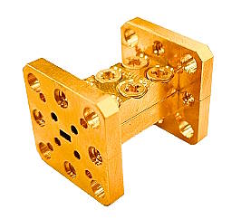
Waveguide filters with harmonic suppression are the key components in many complex mm-wave systems. The video below presents the WR-8 bandpass filter model for 127-139 GHz, while the full product line starts from 26.5 GHz and lasts up to 220 GHz.
This component elevates millimetrer wave labs, telecom R&D, and radar design projects. Explore the forefront of scientific applications, wireless communication and radar systems with high signal integrity, precise harmonic management and low insertion loss.
mm-Wave Waveguide Filters Description
Waveguide filters are crucial components in microwave and millimeter-wave systems, designed to selectively pass or reject specific frequency ranges within the given spectrum. Here’s a description of the key differences between waveguide lowpass, highpass, and bandpass filters within the frequency spectrum from 26.5 to 220 GHz:
- Waveguide Lowpass Filter:
- Function: A lowpass filter allows frequencies below a certain cutoff frequency to pass through while attenuating or rejecting frequencies above that point.
- Operation: In the context of waveguide filters in the 26.5 to 220 GHz range, a lowpass filter would allow signals below a specific GHz value (determined by its design) to pass with minimal attenuation, while signals above this frequency would be attenuated significantly.
- Typical Application: Lowpass filters are often used to remove unwanted harmonics or higher-order frequency components from a signal.
- Waveguide Highpass Filter:
- Function: A highpass filter allows frequencies above a certain cutoff frequency to pass through while attenuating or rejecting lower frequencies.
- Operation: In the specified frequency range, a highpass filter would pass signals above a certain GHz value (determined by its design) with minimal attenuation while attenuating or rejecting signals below this frequency.
- Typical Application: Highpass filters are useful for isolating specific frequency bands or removing unwanted low-frequency components.
- Waveguide Bandpass Filter:
- Function: A bandpass filter allows a specific range of frequencies, known as the passband, to pass through while strongly attenuating frequencies outside of this range.
- Operation: In the 26.5 to 220 GHz spectrum, a bandpass filter would be designed to permit signals within a certain GHz range while attenuating both lower and higher frequencies.
- Typical Application: Bandpass filters are used to select or isolate specific frequency bands of interest, rejecting unwanted interference or noise.
In summary, lowpass, highpass, and bandpass filters in waveguide technology serve distinct purposes. Lowpass filters allow lower-frequency signals to pass, highpass filters allow higher-frequency signals to pass, and bandpass filters permit a specific range of frequencies to pass, all while attenuating other frequencies. The choice between these filter types depends on the specific application’s requirements and the frequency components of interest within the 26.5 to 220 GHz spectrum.
Main characteristics of the WR-8 Waveguide Bandpass Filter with Harmonic Suppression
| WR-8 | 127-139 GHz |
| Rejection level | above 143.5 GHz > 15 dB |
| Insertion losses | 1.5 dB (max.) |
| Custom bands available | Any from 26.6 to 220 GHz |
Typical data for WR-8 Waveguide Bandpass Filter is presented in the plot below:
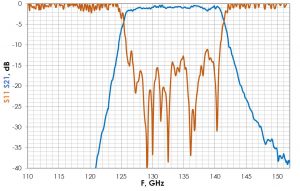
Suppression WR-8 127-139GHz
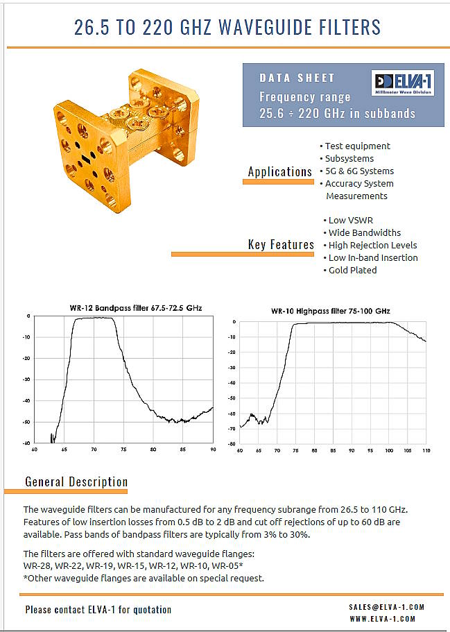
Download this flyer devoted to ELVA-1 waveguide lowpass, highpass and bandpass filters in the frequency spectrum from 26.5 to 220 GHz
How to order
Specify Model Number EAAA-XX/CF/F, where
AAA means the following,
BPF – Bandpass Filter
LPF – Lowpass filter
HPF – Highpass filter
XX – means the designation of the waveguide size corresponding to the operating range,
e.g. 10 = WR-10 (W range, 75-110 GHz), 06 = WR-6 (D range, 110-170 GHz).
The type of waveguide connection flange is as follows
WR-12, 10, 08, 06, 05 – UG-387/U(-M),
WR-15 – UG-385/U,
WR-22,19 – UG-383/U-M,
WR-28 – UG-381/U.
For BPF filter:
CF – center frequency of the operating band in GHz;
F – bandwidth in GHz, by 3 dB.
For LPF, HPF filters
CF – 3 dB cutoff frequency in GHz,
F – suppression frequency in GHz
Product code example
EBPF-08/133/12 means Bandpass filter, WR-8, 133 GHz center frequency, 12 GHz bandwidth
ELPF-10/100/105 means Lowpass filter, WR-10, Passing up to 100GHz, Rejection level above 104.5 GHz >-30 dB
Please feel free to contact ELVA-1 for the EAAA-XX/CF/F mm-wave waveguide filters price.