- Powerful incoherent source
- 1 Watt typical output power in W-band
- High stability
- Good flatness

Applications
- Target illumination in noise radar systems
- Concealed weapons detection systems
- Noise figure measurement
- Instruments and test equipment
- Space and Hi-Rel systems
Description
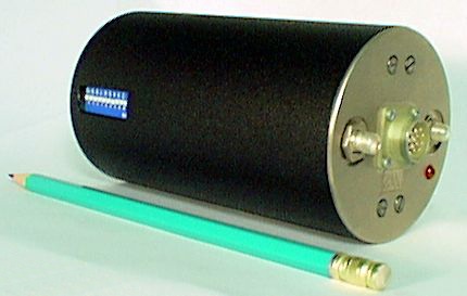
ELVA-1 high power noise sources employ specially designed silicon IMPATT diodes, operating in a pulse mode. It delivers the real incoherent radiation within 5 GHz bandwidth. 1 W level of output power allows to use the device for illumination of targets for the improvement of sensitivity of passive radiometers. The sources are available for all frequencies from 26 to 140 GHz. Low DC power requirements eliminate the need for complex high voltage supplies. The device is supplied with pulsed current source and triggering circuit. Both external and internal triggering modes are provided. Built-in digitally controlled generator allows to install repetition frequency within 10 Hz – 100 kHz range.

Specification
| MODEL NUMBER | PNS -28 | PNS -10 | PNS -08 | PNS -06 |
| Frequency Range, GHz | 26.5-40 | 75-110 | 90-120 | 120-140 |
| Pulse Power Output, W | 1.0 | 0.7 | 0.5 | 0.5 |
| ENR flatness, dB | ±1.5 | ±1.5 | ±1.5 | ±1.5 |
| Pulse width, ns | 60-100 | 60-100 | 60-100 | 60-100 |
| Duty factor | >100 | >100 | >100 | >100 |
| Biasing voltage, VDC | 100 | 48 | 56 | 56 |
- VSWR of the load should not exceed 2:1.
- Operation temperature range -40…+50 °C.
- Specification could be adjusted according to customer requirement.
- Please contact factory for other frequency ranges, bandwidths, pulse lengths and others
- Device is designed in cylinder 120 mm length and 70 mm diameter.
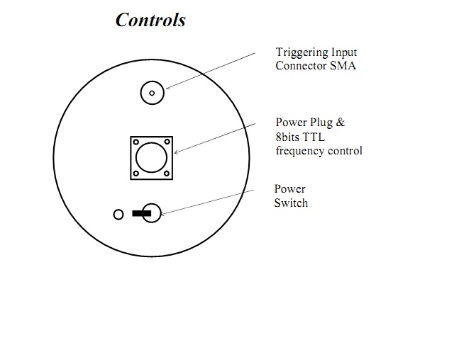
External triggering is available. Special protection scheme is integrated against an application of more then one triggering pulse within 10 μs. To protect the diode the system ignores all pulses during 10 μs period after the last triggering.
The device is supplied with built-in digitally controlled triggering generator with variable repetition frequency within 10 Hz…100 kHz. 256 values of repetition frequency are available. The desired frequency would be installed by dip switches or by 8 bit TTL bus. Pulse duration would be decreased optionally up to 5 ns using fast PIN switch, SPST series. To control the amplitude of the source Voltage Controlled Attenuator VCVA series would be supplied optionally.
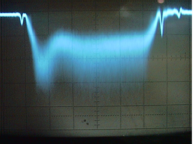
Typical picture of noise pulse measured on the output of detector with 50-Ohm load is presented below:


Integration time of the detector is about 3 ns, scale is 20 ns per division
How to order
Specify Model Number PNS-XX-ABBC, where
XX– waveguide band (WR-Number)
A – flange type, R = round, S = square (WR-28 only)
BB – pulse duration in nanoseconds. Consult ELVA-1 for another pulse duration.
C – AC voltage power supply options. 1 = 110 V AC/60 Hz, 2 = 220 V AC/50 Hz, 3 = 100 V AC/50 Hz


