Features
- 26.5 to 220 GHz
- High sensitivity
- No bias
- Compact design
- High reliability
- Robust design
Applications
- Laboratory measurement and test equipment
- Sensors of mm-wave power
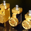
Description
Utilizing a Schottky barrier beam lead diode design, these detectors offer a cost-effective solution for broadband power detection systems. They provide high sensitivity to small signals and maintain a linear response up to -15 dBm. ELVA-1’s ZBD-series Zero Biased Detectors are available in both polarities.
Contact us for details.
Specifications
| Frequency Range (GHz) | 26,5-40 | 33-50 | 40-60 | 50-75 | 60-90 | 75-110 | 90-140 | 110-170 | 140-220 |
| Input Waveguide | WR-28 | WR-22 | WR-19 | WR-15 | WR-12 | WR-10 | WR-08 | WR-06 | WR-05 |
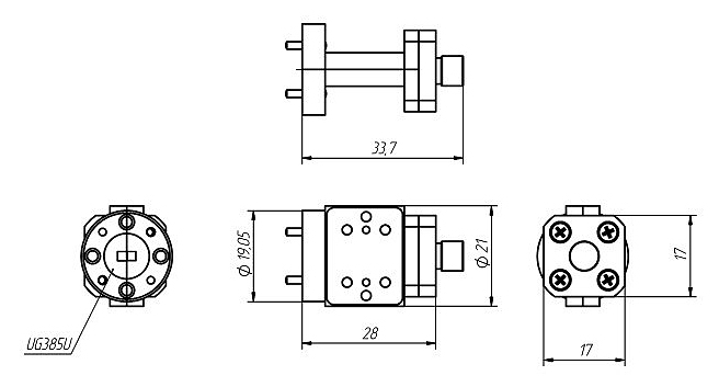
| Waveguide Flange | UG-599/U | UG-383/U | UG-383/U-M | UG-385/U | UG-387/U | UG-387/U-M | UG-387/U-M | UG-387/U-M | UG-387/U-M |
| Sensitivity at –20 dBm Input, 1 Mohm load, mV/mW (typ) | 3500/ 2000 | 3000/ 1500 | 2500/ 1300 | 3000/ 1200 | 1700/ 800 | 1500/ 1100 | 1300/ 800 | 900/ 500 | 500/ 300 |
| Typical Flatness, dB | ±1.5 | ±1.5 | ±1.5 | ±1.5 | ±2.0 | ±2.0 | ±2.5 | ±2.5 | ±2.5 |
| Typical Video Bandwidth, MHz | 10 | 10 | 10 | 10 | 10 | 10 | 10 | 10 | 10 |
| CW Max Input RF Power, dBm | 3 | 3 | 3 | 5 | 7 | 7 | 8 | 8 | 6 |
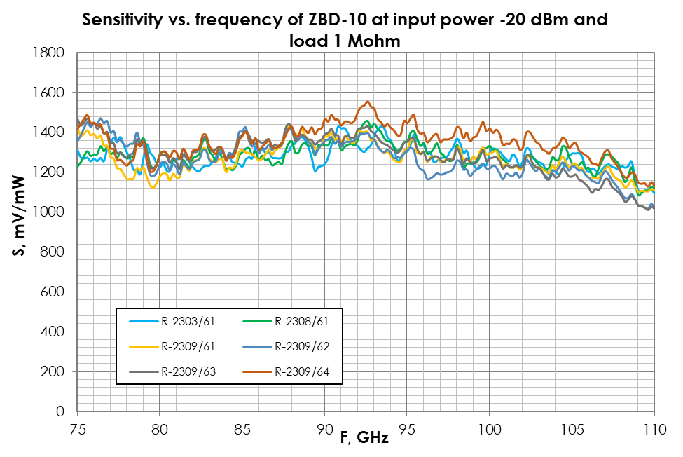
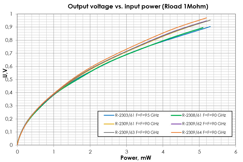
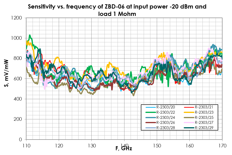
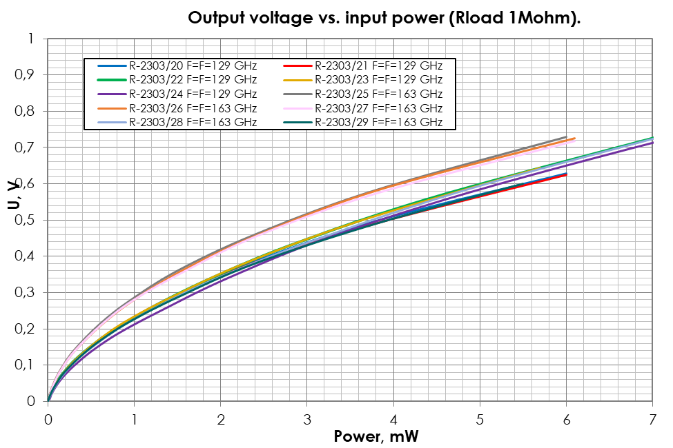
- Typical characteristics of sensitivity with a load resistance of 1 MΩ are presented in the graphs below.
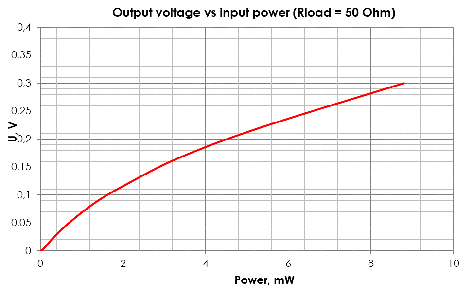
- Typical dependence of output voltage on input power with a load resistance of 50Ω is also presented in the graph.
- To protect the Schottky diode, we recommend using a high-resistance load or a video amplifier.
Note: Max input power level into a detector can be increased by installing the built-in attenuator.
It will cause a decrease in sensitivity correspondingly.
This product design is valid for WR-05 to WR-15 detectors
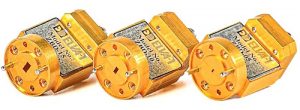
DETECTORS with a built-in video amplifier (OPTION)
Detectors of the ZBDA-XX series come equipped with a built-in video amplifier at the ZBD output. This amplifier serves to protect the Schottky diode against incorrect actions, such as a short circuit at the output or static electricity, thereby enhancing the reliability of ZBDA-XX detectors. These ZBDA-XX detectors operate with a supply voltage in the range of -15VDC to +15VDC. Standard amplifier parameters are presented in the table below

for 60-90 GHz band
Standard amplifier parameters are presented in the table belowЖ
| Bandwidth | Gain | Supply voltage | Max. U output | Note |
| 0-10 КHz | 100 | Unipolar +7…+15 | 4 V | Default model |
| 0-1 MHz | 10 | Bipolar ± (7…15) | 3 V | |
| 0-5 MHz | 10 | Bipolar ± (7…15) | 0.6 V | |
| 0-10 MHz | 10 | Bipolar ± (7…15) | 3 V | |
| 0-200 MHz | 5 | Bipolar ± (7…15) | 3 V |
ZBD-10 typical sensitivity and linearity data
ZBD-06 typical sensitivity and linearity data
Typical dependence of output voltage on input power with a load resistance of 50 Ω:
How to order Zero-Biased Detectors
Specify Model Number ZBD(A)-XX/F/P, where
A – means the output power amplifier added
XX – number of waveguide standard (Ex. 10 for WR-10 and 06 for WR-06)
F – central frequency (or operating range), nothing if full band
P – max input power level in mW
Examples
ZBD-10/20, W-band detector, full operating bandwidth, max input power 20 mW
ZBD-10/92-96/10, W-band detector, operating bandwidth 92-96 GHz, max input power 10 mW
ZBDA-06/140/70, D-band detector with built-in power amplifier, central frequency 140 GHz, max input power 70 mW