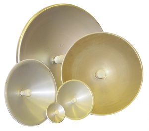
ELVA-1 offers for sale parabolic antennas from 26.5 to 170 GHz for telecom projects and the OEM market.
 ELVA-1 has developed low-cost high-performance millimeter wave Cassegrain antennas to meet the needs of the broadband market. These antennas are dual reflector Cassegrain type ECA – XX series. Antennas of ECA – XX series are available for frequencies from 26.5 to 140 GHz with reflector diameters ranging from 100 to 900 mm.
The gain is up to 53 dBi depending on the frequency. The main reflector has a highly accurate surface and is made of aluminium. The sub-reflector is a machined aluminium hyperboloid or ellipsoid rigidly supported by a special plastic cylinder. These antennas are designed to have minimal cross-section to reduce aperture blockage, and hence produce low sidelobe levels (typically 18 dB). The typical VSWR is 1.25:1. The antenna’s gain depends upon its diameter.
The antenna feed is a circular waveguide of appropriate diameter with an optional circular-to-rectangular transition. D-band antennas for 110-170 GHz are also available by special orders.
Cassegrain Antennas Specifications
for Cassegrain antenna ECA – XX series
Ka-band, 26.5-40 GHz
| Part No | Diameter of main reflector (mm) | Gain dB (typ) | Beam width at 3dB level deg. (typ) | VSWR (typ) |
| ECA-Ka-X-100 | 100 | 26.3 | 6.0 | 1.40 |
| ECA-Ka-X-200 | 200 | 32.7 | 2.9 | 1.35 |
| ECA-Ka-X-300 | 300 | 36.4 | 2.0 | 1.25 |
| ECA-Ka-X-450 | 450 | 40.9 | 1.3 | 1.25 |
| ECA-Ka-X-600 | 600 | 42.9 | 0.9 | 1/25 |
Losses in a Protected cover is 0.7 dB (max)
The feed waveguide is circular or rectangular
Information for Ordering: X= Number for the type of feed waveguide
Available types of Circular waveguides are:
| Number | Frequency Band (GHz) | Diameter of Waveguide (inch) | Flange |
| X=0 | 26.0-28.5 | 0.328 | UG-381/U |
| X=1 | 28.5-33.0 | 0.281 | UG-381/U |
| X=2 | 33.0-38.5 | 0.250 | UG-381/U |
| X=3 | 38.5-43.0 | 0.219 | UG-381/U |
Available type of Rectangular waveguide is:
| X=28 | 26.5-40 | WR-28 | UG-599/U UG-381/U UG-600 |
Data for Gain and Bandwidth are typical for the middle of the frequency range.
Q-band, 33-50 GHz
| Part No | Diameter of the main reflector (mm) | Gain, dB (typ) | Beam width at 3 dB level deg (typ) | VSWR (typ) |
| ECA-Q-X-100 | 100 | 28.3 | 4.8 | 1.40 |
| ECA-Q-X-200 | 200 | 34.6 | 2.3 | 1.35 |
| ECA-Q-X-300 | 300 | 38.5 | 1.6 | 1.25 |
| ECA-Q-X-450 | 450 | 42.9 | 1.0 | 1.25 |
| ECA-Q-X-600 | 600 | 44.9 | 0.7 | 1.25 |
| ECA-Q-X-900 | 900 | 47.0 | 0.4 | 1.25 |
Losses in a Protected cover is 0.7 dB (max)
The feed waveguide is circular or rectangular
Information for Ordering: X= Number for the type of feed waveguide
Available types of Circular waveguides are:
| Number | Frequency Band (GHz) | Diameter of Waveguide (inch) | Flange |
| X=0 | 33.0-38.5 | 0.250 | UG-383/U |
| X=1 | 38.5-43.0 | 0.219 | UG-383/U |
| X=2 | 43.0-50.0 | 0.188 | UG-383/U |
Available type of Rectangular waveguide is:
| X=22 | 33-50 | WR-22 | UG-383/U TRG719 |
Data for Gain and Bandwidth are typical for the middle of the frequency range.
U-band, 40-60 GHz
| Part No | Diameter of main reflector (mm) | Gain, dB (typ) | Beam width at 3dB level deg (typ) | VSWR (typ) |
| ECA-U-X-100 | 100 | 32.0 | 3.9 | 1.35 |
| ECA-U-X-200 | 200 | 38.2 | 2.0 | 1.30 |
| ECA-U-X-300 | 300 | 41.7 | 1.3 | 1.25 |
| ECA-U-X-450 | 450 | 44.8 | 0.9 | 1.25 |
| ECA-U-X-600 | 600 | 46.4 | 0.7 | 1.25 |
Losses in a Protected cover is 0.7 dB (max)
The feed waveguide is circular or rectangular
Information for Ordering: X= Number for the type of feed waveguide
Available types of Circular waveguides are:
| Number | Frequency Band (GHz) | Diameter of Waveguide (inch) | Flange |
| X=0 | 38.5-43.0 | 0.219 | UG-383/U |
| X=1 | 43.0-50.0 | 0.188 | UG-383/U |
| X=2 | 50.0-58.0 | 0.165 | UG-383/U |
Available type of Rectangular waveguide is:
| X=19 | 40-60 | WR-19 | UG-383/U TRG720 |
Data for Gain and Bandwidth are typical for the middle of the frequency range.
V-band, 50-75 GHz
| Part No | Diameter of the main reflector (mm) | Gain, dB (typ) | Beam width at 3dB level deg (typ) | VSWR (typ) |
| ECA-V-X-100 | 100 | 34.0 | 3.1 | 1.3 |
| ECA-V-X-200 | 200 | 39.7 | 1.5 | 1.25 |
| ECA-V-X-300 | 300 | 42.4 | 1.0 | 1.25 |
| ECA-V-X-450 | 450 | 45.4 | 0.7 | 1.25 |
| ECA-V-X-600 | 600 | 47.5 | 0.5 | 1.25 |
Losses in a Protected cover is 0.7 dB (max)
The feed waveguide is circular or rectangular
Information for Ordering: X= Number for the type of feed waveguide
Available types of Circular waveguides are:
| Number | Frequency Band (GHz) | Diameter of Waveguide (inch) | Flange |
| X=0 | 50.0-58.0 | 0.165 | UG-385/U |
| X=1 | 58.0-68.0 | 0.141 | UG-385/U |
| X=2 | 68.0-77.0 | 0.125 | UG-385/U |
Available type of Rectangular waveguide is:
| X=15 | 50-75 | WR-15 | UG-385/U |
Data for Gain and Bandwidth are typical for the middle of the frequency range.
E-band, 60-90 GHz
| Part No | Diameter of the main reflector (mm) | Gain, dB (typ) | Beam width at 3dB level deg (typ) | VSWR (typ) |
| ECA-E-X-100 | 100 | 34.4 | 2.6 | 1.30 |
| ECA-E-X-200 | 200 | 39.9 | 1.3 | 1.25 |
| ECA-E-X-300 | 300 | 43.5 | 0.9 | 1.25 |
| ECA-E-X-450 | 450 | 46.6 | 0.6 | 1.25 |
| ECA-E-X-600 | 600 | 49.5 | 0.4 | 1.25 |
Losses in a Protected cover is 0.7 dB (max)
The feed waveguide is circular or rectangular
Information for Ordering: X= Number for the type of feed waveguide
Available types of Circular waveguides are:
| Number | Frequency Band (GHz) | Diameter of Waveguide (inch) | Flange |
| X=1 | 68.0-77.0 | 0.125 | UG-387/U |
| X=2 | 77.0-87.0 | 0.110 | UG-387/U |
| X=3 | 87.0-100.0 | 0.094 | UG-387/U |
Available type of Rectangular waveguide is:
| X=12 | 60-90 | WR-12 | UG-387/U |
Data for Gain and Bandwidth are typical for the middle of the frequency range.
W-band, 75-110 GHz
| Part No | Diameter of main reflector (mm) | Gain, dB (typ) | Beam width at 3dB level deg (typ) | VSWR (typ) |
| ECA-W-X-100 | 100 | 35.7 | 2.1 | 1.25 |
| ECA-W-X-200 | 200 | 41.7 | 1.0 | 1.25 |
| ECA-W-X-300 | 300 | 45.0 | 0.7 | 1.25 |
| ECA-W-X-450 | 450 | 48.0 | 0.5 | 1.25 |
| ECA-W-X-600 | 600 | 50.0 | 0.4 | 1.25 |
Losses in a Protected cover is 0.7 dB (max)
The feed waveguide is circular or rectangular
Information for Ordering: X= Number for the type of feed waveguide
Available types of Circular waveguides are:
| Number | Frequency Band (GHz) | Diameter of Waveguide (inch) | Flange |
| X=0 | 77.0-87.0 | 0.110 | UG-387/U-M |
| X=1 | 87.0-100.0 | 0.094 | UG-387/U-M |
| X=2 | 100.0-112.0 | 0.082 | UG-387/U-M |
Available type of Rectangular waveguide is:
| X=10 | 75-110 | WR-10 | UG-387/U-M |
Data for Gain and Bandwidth are typical for the middle of the frequency range.
F-band, 90-140 GHz
| Part No | Diameter of main reflector (mm) | Gain dB (typ) | Beam width at 3dB level deg (typ) | VSWR (typ) |
| ECA-F-X-100 | 100 | 37.0 | 1.7 | 1.25 |
| ECA-F-X-200 | 200 | 42.6 | 0.9 | 1.25 |
| ECA-F-X-300 | 300 | 45.9 | 0.6 | 1.25 |
| ECA-F-X-450 | 450 | 48.0 | 0.5 | 1.25 |
Losses in a Protected cover is 0,7 dB (max)
The feed waveguide is circular or rectangular
Information for Ordering: X= Number for the type of feed waveguide
Available types of Circular waveguides are:
| Number | Frequency Band (GHz) | Diameter of Waveguide (inch) | Flange |
| X=0 | 87.0-100.0 | 0.094 | UG-387/U-M |
| X=1 | 100.0-112.0 | 0.082 | UG-387/U-M |
| X=2 | 112.0-125.0 | 0.075 | UG-387/U-M |
| X=3 | 125.0-140.0 | 0.067 | UG-387/U-M |
Available type of Rectangular waveguide is:
| X=8 | 90-140 | WR-8 | UG-387/U-M |
Data for Gain and Bandwidth are typical for the middle of the frequency range.
D-band, 110-170 GHz
| Part No | Diameter of main reflector (mm) | Gain dB (typ) | Beam width at 3dB level deg (typ) | VSWR (typ) |
| ECA-D-X-100 | 100 | 40.3 | 1.4 | 1.25 |
| ECA-D-X-150 | 150 | 43.5 | 0.9 | 1.25 |
| ECA-D-X-200 | 200 | 46.1 | 0.7 | 1.25 |
| ECA-D-X-300 | 300 | 49.4 | 0.5 | 1.25 |
| ECA-D-X-450 | 450 | 52.0 | 0.3 | 1.25 |
Losses in a Protected cover is 1,0 dB (max)
The feed waveguide is circular or rectangular
Information for Ordering: X= Number for the type of feed waveguide
Available types of Circular waveguides are:
| Number | Frequency Band (GHz) | Diameter of Waveguide (inch) | Flange |
| X=0 | 110.0-140.0 | 0.073 | UG-387/U-M |
| X=1 | 140.0-160.0 | 0.059 | UG-387/U-M |
Available type of Rectangular waveguide is:
| X=8 | 110-170 | WR-6 | UG-387/U-M |
Data for Gain and Bandwidth are typical for the middle of the frequency range
How to order your antenna
Specify Model Number ECA-A-X-BBB
A – waveguide band
X – waveguide type
BBB – size of main reflector in mm
Example:
To order antenna meets the following specification: operation frequency 75-110 GHz, in WR-10 waveguide band with UG-387/U-M flange and 300mm of main reflector, should be ordered as ECA-W-10-300.
All ELVA-1 antennas are warranted for one year after receipt.

