- ENR 12…15 dB typical
- High stability
- Good flatness
- No high-voltage supply required
- Compact solid-state source
- High reliability, rugged construction
Applications
- Measurement and test equipment
- Mm-wave noise source
- Calibration
- Noise figure measurement
- Сompatible with noise figure meters for all brand names.
Description
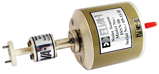
ELVA-1’s calibrated noise source ISSN-XX series delivers a uniform noise power spectral density within the whole waveguide frequency range. Sources are available in eight waveguide bands covering from 26.5 to 170 GHz. A Silicon IMPATT diode is employed as a fundamental building block of the source. The high stability of the device allows it to be used for test and instrumentation applications in place of gas-tube noise sources. Low DC power requirements eliminate the need for complex high-voltage supplies. Two operation modes are CW (continuous wave) mode and pulsed AM mode with modulation frequencies up to 1 kHz. A typical value of excess noise ratio (ENR) as a function of frequency is given in the plot below.
Block Diagram of Noise Source

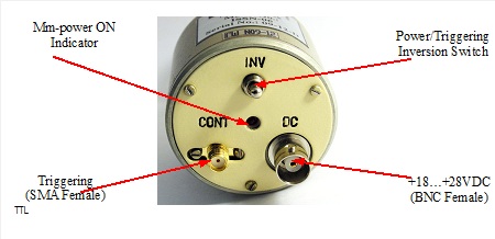
Inputs and Controls:
Notes:
- Power/Triggering Inversion Switch can be used for manual ON/OFF. “INV” position is ON.
- The microwave power can be switched with TTL-level control voltage.
- If the Triggering Inversion Switch is in OFF (Down) position active level is high, otherwise (INV position) – the active level is low.
- Each source supplied is calibrated relative to the liquid nitrogen-cooled load.
Specifications
| Model Number | ISSN-28 | ISSN-22 | ISSN-19 | ISSN-15 | ISSN-12 | ISSN-10 | ISSN-08 | ISSN-06 |
| Frequency Band | Ka | Q | U | V | E | W | F | D |
| Range, GHz | 26.5-40 | 33-50 | 40-60 | 50-75 | 60-90 | 75-110 | 90-140 | 110-170 |
| Output waveguide | WR28 | WR22 | WR19 | WR15 | WR12 | WR10 | WR8 | WR6 |
| Waveguide Flange | UG599/U | UG383/U | UG383/U-M | UG385/U | UG-387/U | UG387/U-M | UG387/U-M | UG387/U-M |
| Bandwidth, GHz | Full | Full | Full | Full | Full | Full | Full | Full |
| ENR, dB (nom) | 15 | 14 | 13 | 13 | 13 | 12 | 12 | 12 |
| ENR Flatness, dB | ±1.0 | ±1.5 | ±1.5 | ±1.5 | ±1.5 | ±1.5 | ±2.0 | ±2.5 |
| Stability, dB/°C | 0.01 | 0.01 | 0.01 | 0.01 | 0.01 | 0.01 | 0.01 | 0.01 |
| Stability/Day, dB | 0.05 | 0.05 | 0.05 | 0.05 | 0.05 | 0.05 | 0.05 | 0.05 |
| Biasing Voltage, V | +18…+28 | |||||||
| Sizes, mm* | 50/75 | 50/75 | 50/75 | 50/75 | 50/60 | 50/60 | 50/60 | 50/60 |
| * Cylinder diameter/length (without isolator) | ||||||||
Notes:
- Maximum operating temperature is +60 °C
- Diode operating current is 50…100 mA.
- A limiting value of modulation frequency is 1 kHz (external triggering).
- Triggering signal amplitude is TTL level.
- The bias voltage is +18 V It is possible to supply the noise source with +28 V DC biasing for compatibility with commonly used noise meters.
- The external triggering connector is SMA female
- ENR would be increased for narrower bandwidth. Please get in touch with the factory.
- For higher-frequency models please get in touch with the factory.
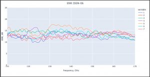
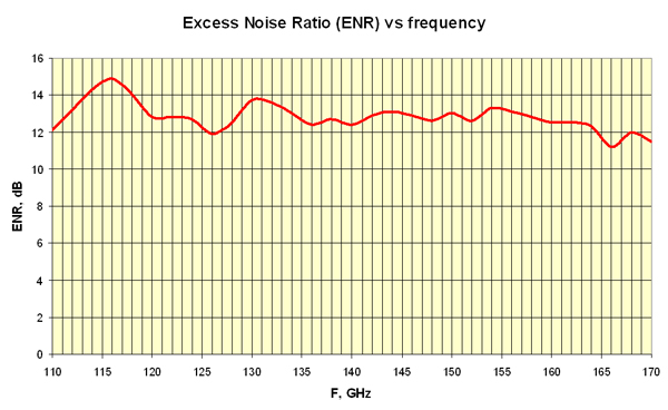 The below chart shows the ENR value of different ISSN-06 units (i.e. the parameters in a batch of the same type of units). This is to show that ISSN-06 does not have more than 2.5 dB difference in the ENR parameter.
How to order
Specify Model Number ISSN-XX/BW/V, where
XX – number of waveguide standard (Ex. 10 for WR-10 and 06 for WR-06)
BW – operating bandwidth in GHz (nothing if full band)
V – type of power supply: 18 or 28 if external power supply +18 V DC or +28 V DC of customer’s lab will be used (specify voltage), 110 or 220 if external 110 V AC or 220 V AC power supply is requested together with the noise source
Examples
ISSN-10/28 ( W-band noise source with output waveguide WR-10, full band 75-110 GHz, external power supply +28 V DC not requested
ISSN-06/110-140/220 ( D-band noise source with output waveguide WR-06, operating frequency 110-140 GHz, external 220VAC power supply requested as well

