Power up your project with a high-performance Voltage Controlled Oscillator (VCO). The frequency of this electronic oscillator is controlled by a voltage input, which means you can determine the oscillation frequency with precision.
Need help choosing the right VCO model for your project? Let ELVA-1 be your guide. Consult with us anytime – we’re here to support you.
| Features |
 |
- High output power
- Digital/Electrical Frequency control
- High power and frequency stability
- Digital/Electrical control of output power
|
- The ability of long-term frequency stability
- Stable spectrum
- The ability of remote control/diagnostics via the internet
- Long lifetime
|
| Applications |
 |
- EPR spectrometer bridge
- DNP polarizer source
- Measurement and test equipment
- Mm-wave source of high power
- Plasma diagnostics
|
| Description |
|
Millimeter-wave oscillators of VCOM-XX series originally was designed for purposes of EPR spectroscopy and plasma diagnostics. It provides electromagnetic energy within some range around central frequency with high output power. The original design uses low frequency stable voltage-controlled oscillator and frequency multiplier. To increase output power an IMPATT mm-wave power amplifier can be used. The max value of the output power level depends on the requested frequency range. It can be 200 mW at
94 GHz, 50 mW at 140 GHz and 10 mW at 170 GHz. |
| Output power and frequency are controlled by means of digital code signal (symbol D at end of p/n: VCOM-…-DD, VCOM-…-DA, VCOM-…-DP models) or with external DC or pulse voltages (VCOM-…-T, VCOM-…-DA, VCOM-…-DP models). Digital control models of VCOM-XX have built-in frequency counter that allows for providing high long-term stability of output frequency. Also, remote control and diagnostics of operation through the internet are admissible. |
| The stable operation of VCOM-XX oscillators allows them to be used in scientific experiments that last for a long time, many months and years. Models with the D index can track and adjust their frequency automatically, keeping its set value indefinitely. |
| |
| There are a set of standard models of the VCOM-XX oscillators now. |
- T – analogue control of frequency and power level
- TV – is based on the -T model. But -TV is customized to the customer’s requirements and differs from the standard -T model:
– the presence of the indicator
– the presence of a potentiometer for manual adjustment of frequency
– the presence of a power output +12 V to connect the frequency doubler.
- DD – digital control of frequency and power level
- DA – analogue and digital control (switchable modes)
- DP – digital control of output frequency, digital and analogue control of power level (up to 5kHz pulse modulation of power level available).
|
| ATTENTION: Custom-designed VCOM models can be produced by your order. |
| Specifications |
| MODEL |
VCOM-10/94/0.5/200-XX |
VCOM-06/140/2/20-XX |
VCOM-06/170/2/10-XX |
| Central frequency |
94 GHz |
140 GHz |
170 GHz |
| Bandwidth |
500 MHz |
2 GHz |
2 GHz |
| Frequency Range (controlled) |
93.75-94.25 GHz |
139-141 GHz |
169-171 GHz |
| Output power (controlled) |
0-200 mW |
0-20 mW |
0-10 mW |
| Spectrum line width at -3dBc |
100 kHz max |
100 kHz max |
100 kHz max |
| Control attenuation |
0…50 dB |
0…50 dB |
0…40 dB |
| Flange/ Waveguide |
UG-387/U-M /WR-10 |
UG-387/U-M /WR-06 |
UG-387/U-M /WR-06 |
| Operating Humidity in Temp range of +10 to +40 °С |
< 70% (non-condensing) |
< 70% (non-condensing) |
< 70% (non-condensing) |
| For models with digital control: |
|
|
|
| Frequency Step (max) |
250 kHz |
350 kHz |
500 kHz |
| Power Level Step |
< 1 mW |
< 0.1 mW |
0.05 mW |
| Absolute accuracy of set Frequency in range of +10 to +40 °С |
<0.5 MHz |
<0.7 MHz |
<1 MHz |
| Settling time to major frequency step within 0.5 MHz |
less than or equal to 500 ms (max) |
less than or equal to 500 ms (max) |
less than or equal to 500 ms (max) |
| Long term stability of reference crystal oscillator at constant temperature |
+/- 1 ppm per month |
+/- 1 ppm per month |
+/- 1 ppm per month |
| Output Frequency/Power Control connector |
RS232/DB-9 Plug |
RS232/DB-9 Plug |
RS232/DB-9 Plug |
| Remote Diagnostic Protocol |
Ethernet/SNMP v1 |
Ethernet/SNMP v1 |
Ethernet/SNMP v1 |
| Ethernet port: |
RG-45 Socket |
RG-45 Socket |
RG-45 Socket |
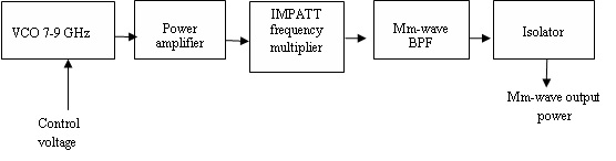
| Basic block schemes of VCOM oscillator: |
| A. Wideband VCOM…-T (does not have powerful output power amplifier which limits operating bandwidth): |
 |
| B. High power VCOM…-DD with digital control and remote control/diagnostics: |
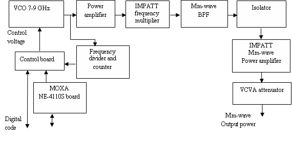 |
 |
 |
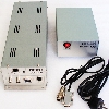
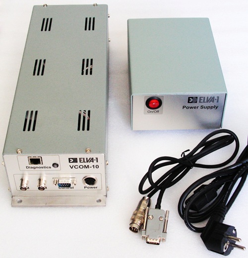
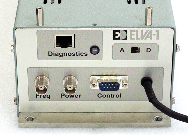
| A) |
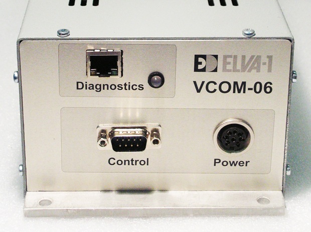
B) |
| Control panel of VCOM-10/94/0.5/200-DA (a) and VCOM-06/140/0.5/50-DD oscillators (b) |
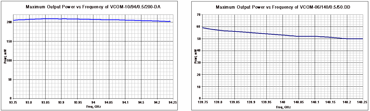
| Typical measured data of W- and D- band VCOM-XX oscillators: |
 |
- How to order
- Specify Model Number VCOM-XX/CF/BW/P-AB, where
- XX – number of waveguide standard (Ex. 10 for WR-10 and 06 for WR-06)
- CF – central operating frequency in GHz
- BW – operating bandwidth, GHz
- P – output power (nom.), mW
- AB – type of output frequency and power control: -T or -DD, or –DA or -DP
- Standard flange is UG-XXX/U-M round
- Example
- VCOM-10/94/0.5/200-DD ( W-band oscillator, WR-10 waveguide, Central frequency 94 GHz, Bandwidth 0.5 GHz, Output power 200 mW (typ.), Digital control of output power and frequency).