| Features | |
|
|
| Applications | 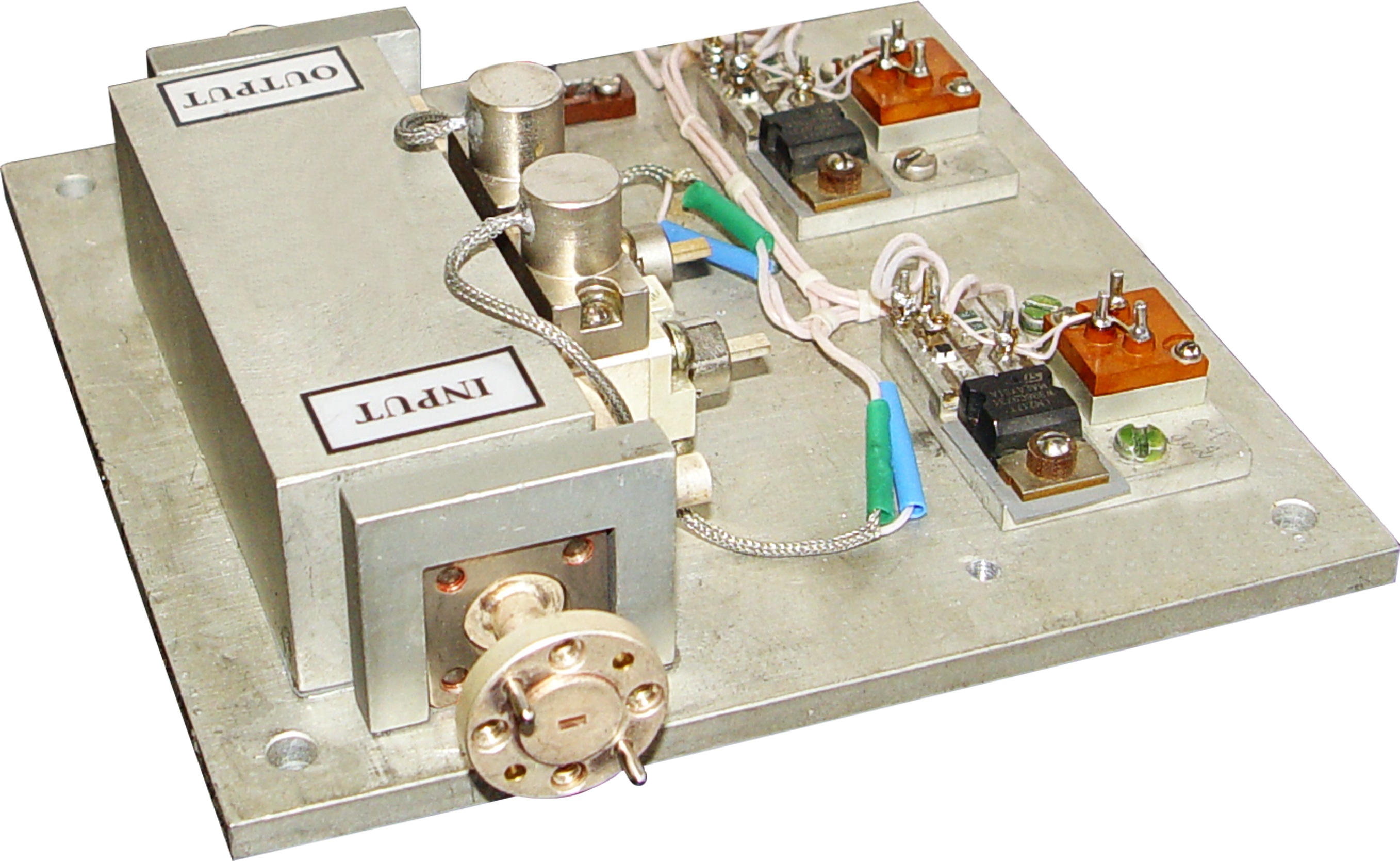 |
|
|
| Description | |
| ELVA-1 Injection-locked Amplifiers IILA-XX series are intended for high-power amplification of CW and pulse mm-wave signals. They are offered in the frequency range from 26 to 150 GHz in five waveguide bands. They can operate from power level as low as 2-3 mW which can be obtained directly from Up-Converter or frequency multiplier. When IILA-XX amplifier is injection locked FM noise of the output is the same as the input injection signal. In the absence of an in-band input signal of sufficient power to attain injection lock, there is a free running output signal.
The amplifiers are provided with integral circulators and DC voltage regulator. An operational heater is available for better temperature stability. To achieve higher gain, broader locking bandwidth and higher output, multistage and multi-diode configurations are also available. Reliable work of IILA-XX oscillators allows using them in scientific experiments which last for long time, a few weeks or even months. Custom designed IILA-XX models can be produced by special order. |
|
Specifications
| MODEL NUMBER | IILA-22 | IILA-15 | IILA-10 | IILA-06 |
| Central frequency in range, GHz | 40-50 | 50-75 | 75-110 | 110-150 |
| MAX cw power, mW (typ) | 200 | 200 | 200 | 100 |
| Max pulse power, W | 15 | 15 | 10 | 2 |
| Injection locked bandwidth at -1dB level, MHz | 300 | 400 | 500 | 500 |
| Power output flatness, dB (typ) | +/-1 | +/-1 | +/-1 | +/-1 |
| Waveguide | WR-22 | WR-15 | WR-10 | WR-06 |
| Flange | UG-383/U | UG-385/U | UG-387/U-M | UG-387/U-M |
| DC Power, V/A | +45/0.4 | +32/0.4 | +27/0.4 | +24/0.4 |
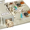
| Typical measured data of IILA-94/1.0/200/15 amplifier: | |
 |
|
 |
|
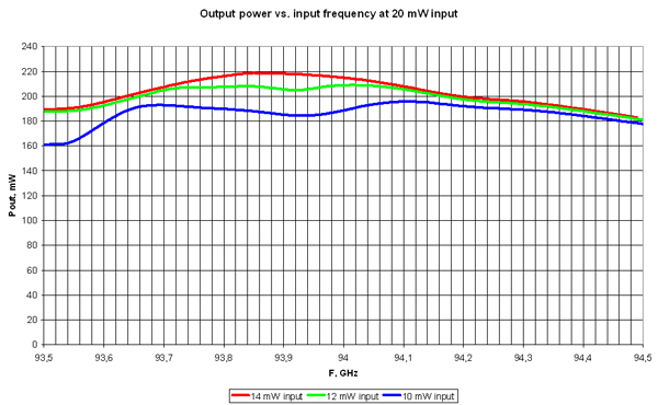
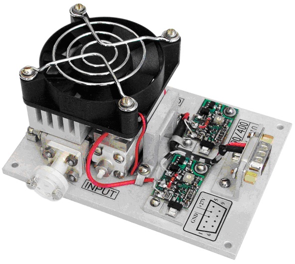
Photo of 400 mW power amplifier produced for special request
Input power 160 mW, output power 400 mW, F=90 GHz
How to order
Specify Model Number IILA-XX/CF/BW/P/I, where
XX – number of waveguide standard (Ex. 10 for WR-10 and 06 for WR-06)
CF – central operating frequency in GHz
BW – operating bandwidth, GHz
P – output power (nom), mW
I – input power (nom), mW
Example
IILA-10/94/0.5/200/20 ( W-band IMPATT injection locked amplifier, WR-10 waveguide, Central frequency 94 GHz, Bandwidth 0.5 GHz, Output power 200 mW (typ), Input signal 20 mW