
ELVA-1 successfully tested 71-76/81-86 GHz E-band wireless radios for V2X / V2N communications. The technology was recognized as workable on roads, including promisable for self-driving cars and driverless rail transport.
In 2020, FCC proposed extending 70/80 GHz communications to aircraft and ships, recognizing the great potential for E-band communications in the transportation industry. Here is a remark about ships and aeroplanes: it looks illogical that the FCC document does not mention trains, buses and trams, which today also carry many passengers with smartphones, tablets and laptops.
It looks like the FCC was impressed by the Aquilla project (2016) by Facebook, in which giant solar-powered drones from an altitude of 18 – 27 km were supposed to distribute Internet access using the 70/80 GHz E-band for client points on the ground and in the air. The Aquilla project, as may you know, got just a pilot stage and Facebook shut it down in 2018. But the idea remained very clever as innovations from Facebook.
ELVA-1 team closely observed the achievements of Facebook Connectivity Lab in the Aquilla project in terms of E-band radio communications. For example, did analyzing the article about testing of 20 Gbps 70-80 GHz 8-mile wireless link( Facebook Connectivity Lab Demonstrates 20 Gbps Wireless Broadband Over An 8 Mile Area ), comparing it with the capabilities of their 70-80 GHz radio links implemented on distances 15, 16 and even 19.5 km (and the most high-performance commercial mm-wave radio link in the industry which shows a throughput of 60 Gbps for 11 km.
ELVA’ Idea of 10 Gbps Communications to Moving Car
Why not try for ourselves how well 70/80 GHz radio communication will work on moving objects? This is a story of how the team decided to start their experiment with mobile communication on PPC-10G 10Gbps 70-80GHz links modified for V2N/V2X vehicle-to-ground connectivity.
It was decided to try the PPC-10G 10 Gbps 70-80 GHz communication system on a passenger car. This type of communication is called V2N (Vehicle to Network) and is positioned as particularly promising in the transportation industry, including self-driving cars and driverless rail transport (driverless loco, driverless tram, etc..).
According to engineers, the idea of V2N/V2X communication 70/80 GHz (71-76 / 81-86 GHz) looked complicated due to the traditional practice of using antennas that form a rather narrow radio beam. Even when installed on fixed supports (towers, roofs), antennas must be precisely adjusted. But it was decided to try using the horn type antennas on a vehicle.
In 2022, it has been 19 years since the FCC in the United States first designated the 71-76 / 81-86 GHz (E-band 70-80 GHz) frequency spectrum for fixed wireless communications. Almost immediately, regulators in other countries followed FCC regulations. Today 1 to10 Gbps E-band radios are very popular for fixed wireless communications worldwide.
Testing 70-80 GHz V2X/V2N communications using a vehicle
It was decided to implement the idea of using 71-76 / 81-86 GHz radios for 10-gigabit V2N communications using antennas with different directional patterns. I.e., for fixed base stations, use radios with narrow-directional parabolic antennas, and install the same radios with miniature horn antennas with a wider radiation pattern on a vehicle.
A passenger car can simulate city public transport (bus, light rail tram, etc.), and such an experiment allowed the ELVA-1 team to test the quality of communication with the various antenna options and the effect of the type of signal modulation on the stability of communications.
The experiment on 70-80 GHz V2N communications was based on a passenger car moving along the runway. For the experiment, the airfield administration was authorized ELVA-1 to use half of the total runway length (1/2 of 2.3 km).
")

On the runway, at a distance of 1.14 km from each other, two base stations BS1 and BS2 of the PPC-10G-E-30 model were located. The parabolic antennas were with a diameter of 30 cm. The car moved between these base stations in the centre of the runway.
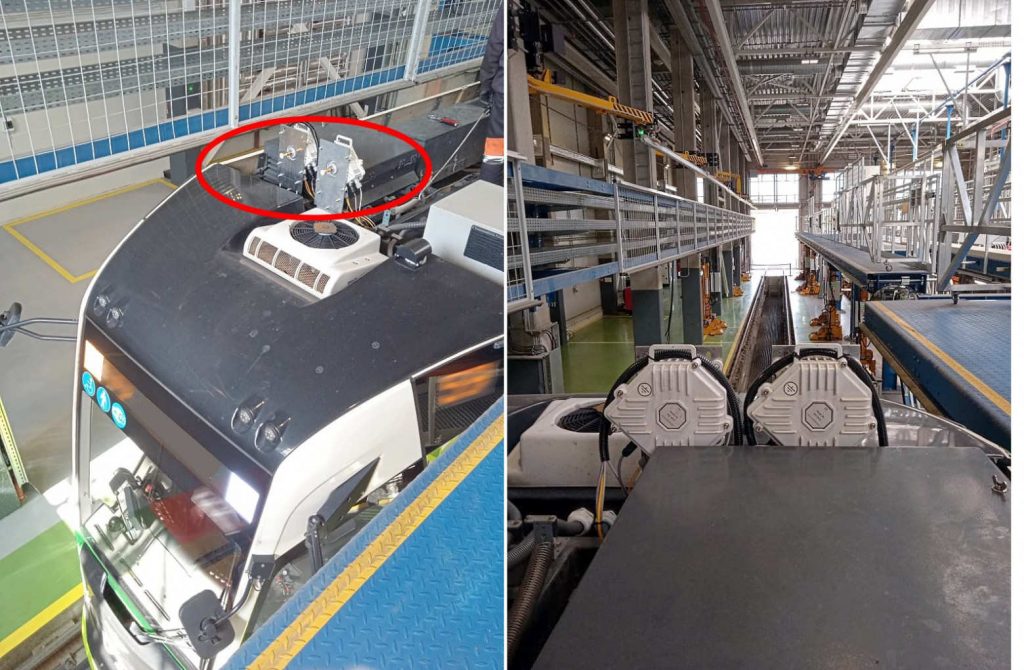
On the roof rails of the car, PPC-10G transceivers of the 71-76 / 81-86 GHz band were installed with miniature horn antennas directed forward and backwards along with the car. Thus, the situation was simulated when such transceivers are installed in the head and back of a bus, a train or a light rail for wireless communication with base stations in the forward and backward directions.
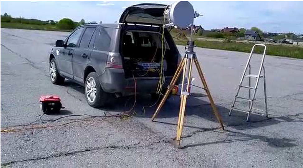
Power cables from a portable generator, as well as Ethernet and SNMP monitoring cables, were connected to each base station. The connection between the base stations BS1 and BS2 was carried out via an additional fixed 10 Gbps radio.
A preliminary calculation of all radio parameters was carried out, depending on the location of the car between the base points, using ELVA-1′ link budget calculator for E-band. Using this software, engineers calculated the level of the signal (RSL, Receiver Signal Level) and the corresponding throughput of the radio.
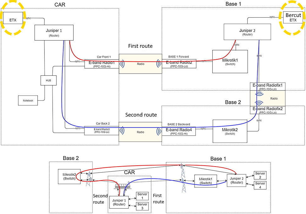
In the first experiment, two independent radio channels were involved, one with an antenna directed forward in the direction of the vehicle’s movement, the other with an antenna in the opposite direction. In this experiment, the data transfer rate, the number of lost packets and errors were measured using Bercut-ETX traffic analyzers. Block diagram of the first experiment
Three type of experiments were performed, each with its own set of car runs. The test equipment was connected according to their operation manual. In this case, one of the testers worked in the generator-analyzer mode. The generator created test traffic with the MAC and IP address of the second tester.
The description of the first experiment is as follows: the test data were sent to the tested network, while the traffic through the wireless channel and the router were received by the second tester, which worked in loopback mode. The test stream unrolled and test traffic with the MAC and IP addresses of the first tester was sent back to the network. Traffic was again transmitted over the wireless channel and routing scheme. The first tester received data in which it did checks for errors and lost packets. The results of losses for different packet sizes are shown in the table for the parameters “Frame-packet size; Rate-channel load. Loss-packet loss”.
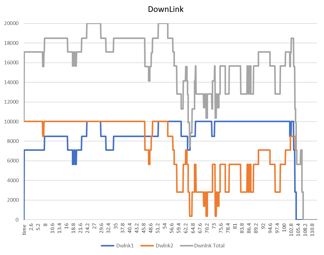
The results for download/upload traffic are presented in the graphs below. The data transfer rate through the front module (Dwlnk1 / Uplnk1) is a blue line, through the back (Dwlnk2 / Uplnk2) – a yellow, grey graph (Dwlnk / Uplink Total) is the result of the mathematical sum of one and the second channel. In this experiment, the traffic from two radio channels did not add up; the traffic transmission rate in both radio channels was measured independently in full-duplex mode.
| Frame loss | |||
| Frame | Rate,% | Loss,% | Loss, Mbps L1 |
| 64 | 100 | 0 | 0.0001 |
| 128 | 100 | 0 | 0.0001 |
| 256 | 100 | 0 | 0.0004 |
| 512 | 100 | 0 | 0 |
| 1024 | 100 | 0 | 0 |
| 1518 | 100 | 0.296 | 29.6039 |
| 10000 | 100 | 1.1756 | 117.5594 |
| 14000 | 100 | 1.2206 | 122.0633 |

In the second experiment, it was measured the throughput of a large file transfer between servers over the air to the moving vehicle (V2X/V2N concept). For example, such communication is important for self-driving cars, allowing real-time changes to the driving route due to changed traffic conditions.
Cincoze DS-1202 embedded industrial computers were used as servers. To provide a total load of true 20 Gbps tp the communication system it was necessary to deploy two pairs of servers. The first pair of servers were used for radio communication in the forward direction of the car and the second pair of servers for traffic in the opposite direction (backwards). Two pairs of servers were required to load a full10 Gbps flow for each of the two wireless data paths.
It turned out to be a difficult task to send files from the server to the wireless channel at such a speed that the true 10 Gbps bandwidth of each of the radio channels. To do this, we cyclically uploaded a large file from the RAM disk to ensure the required transfer rate.
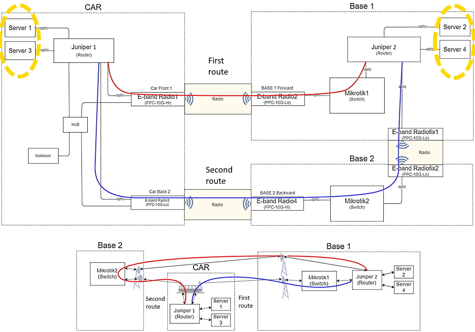
On the BS1 side (Base Station #1), two data transmission servers, Juniper routing equipment and Mikrotik were placed in a stationary car to ensure communication with the BS2 (base station #2). In the moving car, 2 servers were also installed, each with a transmission speed of 10 Gbps. The distribution and routing of Cincoze server traffic were handled by Juniper routers.
Traffic was transmitted along two physical routes, including the wireless connection with the car:
- The first route in the head direction: Server 1 & 3 -> Juniper1 -> E-band Radio1 ->
E-band Radio2 -> Mikrotik1 -> Juniper2 -> Server 2 & 4. - The second route at the car’s back direction: Server 1 & 3 -> Juniper1 ->
E-band Radio3 -> E-band Radio4 -> Mikrotik2 -> E-band Radiofix2 -> E-band Radiofix1-> Juniper2 -> Server 2 & 4.
For the second experiment, instead of the Bercut-ETX tester-analyzers, we used Cincoze servers (servers #1 and #2). These places are marked with yellow dotted lines in the diagram.
When the car was moving, the total throughput of the communications system was measured, taking into account the routing and summation of traffic between the servers in the car and stationary servers. We used a special firmware and a proprietary utility to record the state of the radio channel while the car was moving, with 10 times per second data recording for the radio modules.
In the following figure, the graphs of one of the car pass of the second experiment, the signal level at the receiver input and traffic in the direction of the car’s movement are shown in blue, in the opposite direction – in red.
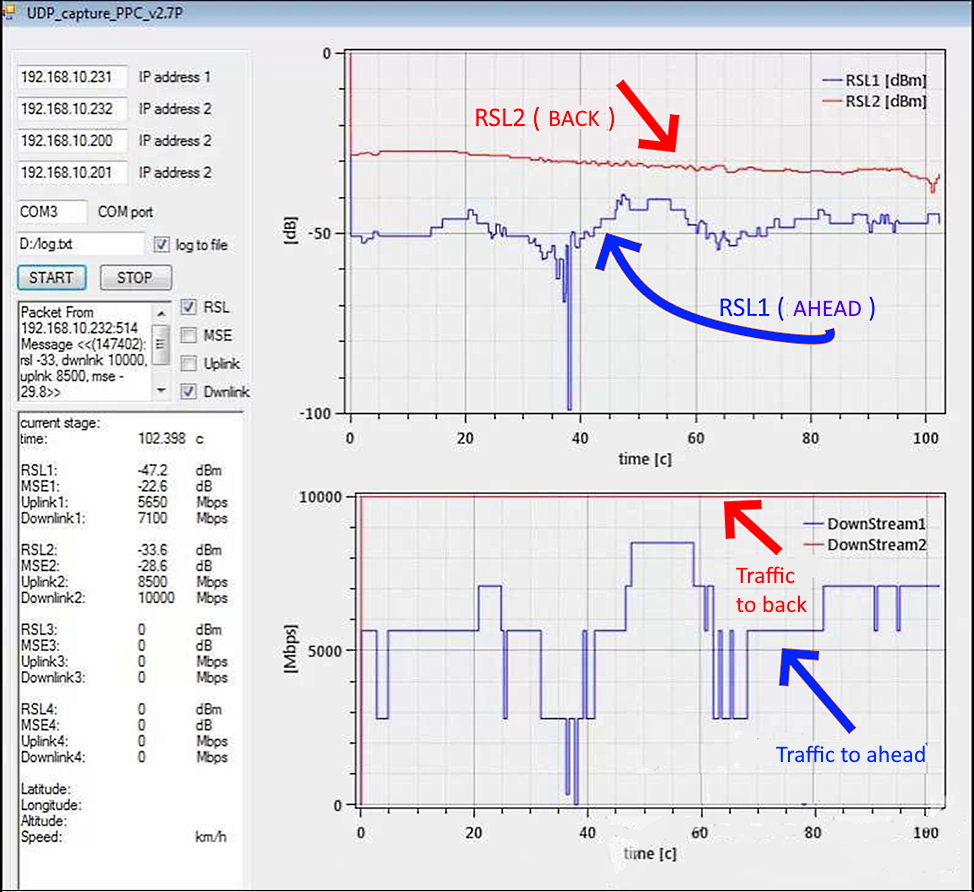
At the top of the graph (RSL), the signal level at the receiver input was recorded, which makes it possible to evaluate the quality of the connection. The stability of the connection in the opposite direction (RSL2) was better, in the forward direction (RSL1) —worse, with a dip (at 38th second) and a greater amplitude of the signal change.
Explanation of the graph: This graph covers the first 100 m of the route from one base station to another. The car moves from the base station, which is behind the vehicle at a distance of less than 100 m, to the one in front, at a distance of about 1 km. Therefore, the signal in the direction “back” to the nearest base station is better in terms of parameters.
The bottom graph (DownStream) shows the data traffic. The situation is similar, only the steps are larger since if the input signal level (RSL) is insufficient, the modulation profile is automatically switched from QAM-128 to simpler modulation types (QAM-64, QAM-32, etc.) to maintain the connection working.
An additional illustration of the quality of the mobile connection is shown in the screenshot from the Mikrotik ports.
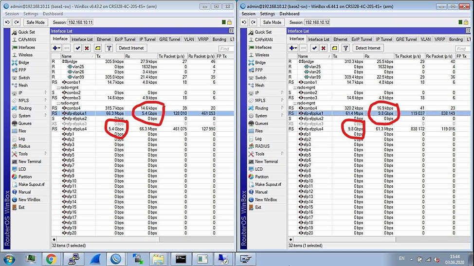
Explanation of the transfer rate on Mikrotik: on the left side, Mikrotik1 routes the physical route forward, the value of the transfer rate of 5.4 Gbps is recorded. On the right side, Mikrotik2 routes the radio channel in back direction, the transmission rate of 9.8 Gbps is recorded.
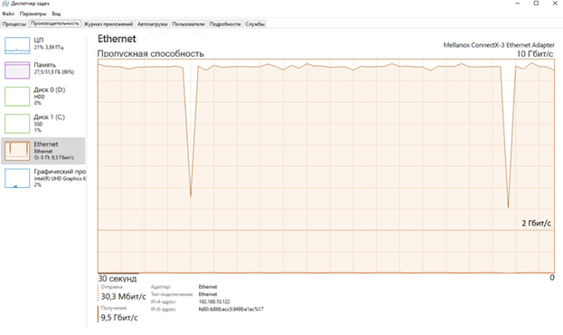
There is also a graph from the Windows Task Manager for the channel loading when transferring files. For clarity, a graph was obtained during a cyclic transfer of a 10 GB file located in RAM (RAM-disk). Dips in traffic transmission may be explained by the peculiarities of the operating system during the operations of the end of recording, the beginning of reading a file.

Below, solely for comparison purposes, is the result of a similar control experiment where the same servers were connected by a short optical patch cord on a table. At the same time, neither the routing systems nor the radio channels on the car were used.

Explanation of the file transfer charts: during the experiment, it was not possible to provide traffic for both 10 Gbps channels using one pair of servers to obtain a total flow of 20 Gbps.
Since each server generates a data stream with one IP address and one logical port number, the ECMP (Equal cost MultiPath) traffic balancing algorithm perceives such data as one stream and transmits it only through one route, which means through one physical channel. Therefore, the maximum data transfer rate for one server did not exceed 10 Gbps.
When transmitting data from two servers with different IP addresses, traffic is distributed over two channels, in this experiment – forward and backward along the direction of the car. This ensures the maximum throughput of the communication system of 20 Gbps. In the event of a break in one of the channels, all traffic is switched to the other channel.
In the third experiment, similar to the second, the traffic between the servers was measured when the data transmission channel was loaded using the low-level utility Iperf while driving.

ELVA-1 Assesment for V2X/V2N Car Test in the 70-80 GHz Band
Depending on the type of traffic generator equipment, the following results were obtained:
- When using analyzers of Bercut-ETX model, (Frame losses, BER-test), regardless of the size of data packets, the transmission rate is 10 Gbps, packet loss is not higher than 0.3% for standard packets and not higher than 1.3% for large data packets.
- When using the IPerf utility, the transfer rate of the test data stream is fixed at 9.35 Gbps.
- When using the transfer of data files from one RAM-disk to another RAM-disk server (Ethernet statistics), the connection speed averaged around 7 Gbps on one pair of servers and 9.6 Gbps on the second pair of servers. The traffic value of 7 Gbps is explained by the fact that the base starion in this case was located at a considerable distance from the car (the radio channel in the forward direction), and the base station with a 9.6 Gbpsexchange rate was located close to the car (the radio channel in the direction back”).
In experiment #3, the TCP/IP protocol was used to transfer files. At the same time, in experiments #1 and #2, the UDP protocol was used, the UDP protocol does not reduce the speed even with single packet losses, and the TCP/IP protocol is sensitive to uneven bandwidth of the channel.
How ELVA-1 10 Gbps V2X/V2N E-band system worked on a real road
In addition to experiments on the runway of the airfield, the races were also carried out on a flat section of the road. The maximum transmission distance and bandwidth of the communication channel were tested at high vehicle speeds. The results turned out to be very optimistic, 10 Gbit / s communication was recorded 500 m from the base station, and the total communication range, subject to line of sight, was at least 2 km.
Summary for V2X/V2N Communications Car-to-Network Test in the 70-80 GHz E-Band
The experiment with the organization of mobile communication V2X (“a car for everything”) made it possible to prove the efficiency of the idea:
- For the frequencies 71-76 / 81-86 GHz, the practical possibility of transmitting a data stream to a moving vehicle with a bandwidth of up to 10 Gbps is shown .
- The distance of stable communication in the experiment on the road is up to 2.5 km at a transmission rate of 2 Gbps, and in tests on a countryside road, a connection of 10 Gbps was achieved already at a distance of about 500 m between the vehicle and the base RRS.
Thus, the idea of using 71-76 / 81-86 GHz wireless equipment for V2X/V2N communication was recognized as workable and the prerequisites were created for testing on real routes in the transportation industry.